
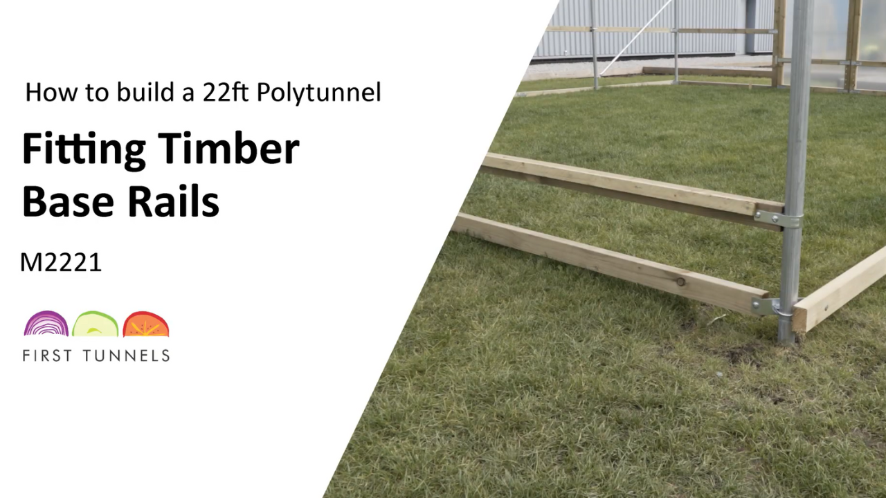

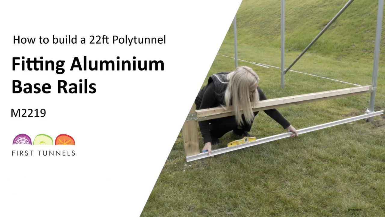


Base rails are made up of timber rails measuring 47mm x 75mm, commonly known as 3 by 2. They are supplied in lengths of 1.8m, 2.4m and 3.2m long. They consist of four corner rails 2.4m long (TBR24). The two side rails are supplied in 1.8m and 3.2m lengths (TBR18 & TBR32). The base rails fix along the length of the polytunnel, on the outside of the framework with the 47mm dimension facing towards the ground. On the end of the tunnel the base rails fit on the inside, so that the outer face is in line with the outside of the framework and flush with the door post upright (fig 19a).
NOTE: You will be required to cut to size.
The timber rail is attached to the framework using intermediate brackets (ICT50) and corner brackets (CCT50) with any joints secured with nail plates (NP3). Start by fitting the base rail down the length of your polytunnel. If your Polytunnel has a slope, across the width, then we suggest fitting the rail on the side that is highest first (fig 19b). Your foundations will have been positioned at a consistent height and consequently the swage joint can act as an indicator for the position of the rail. Set the base of the rail in line with the joint on the foundation (fig 19c).
Fit a corner clamp (CCT50) to the end hoop To assemble the corner clamp, place the U bolt around the corner hoop with the threads pointing towards the inside of the polytunnel. Place the tube pressing then corner clamp onto the threads. Ensuring the corner clamp wings run parallel to the width and length of the polytunnel and loosely secure in place (fig 19d).
Locate a length of 3.2m timber (TBR32) and position it down the length of your polytunnel at ground level. Make one end flush with the end of your polytunnel. Set your base rail at ground level, in a consistent line, do not follow the undulations of the ground. Setting the bottom of the timber in line with the swaged joint will achieve this.
Ensure the wing of the corner clamp is in the centre of the timber and that the timber is on the outside of the corner clamp wing and make a mark on the timber through the corner clamp wing. Drill a hole through the timber on this mark using a 9mm timber drill bit. Push a bolt through the timber and corner clamp ensuring the thread is on the inside of the polytunnel and secure in place with a nut.
To secure the base rail to the intermediate hoop use an intermediate clamp (ICT50) . Drill a hole through the timber on each side of the hoop using a 9mm timber drill bit. Place a bolt through each of these holes from the outside (fig 19e). An arched pressing is placed over the bolts and secured in place with nuts. To add another section you will need to join another piece of base rail to the one you have just fitted. To join the pieces of base rail you will be required to fit a nail plate to each side of the joint (NP3) (fig 19f) . Position a nail plate equally across the joint and then secure in place using square twisted nails. Work down the length of your polytunnel joining sections of 3.2m (TBR32) long base rail finishing with a 1.8m if required and securing them to the hoops using clamps. The base rail will exceed the length of your polytunnel and will be cut off later.
To fit the base rail from the door post to the corner hoop. Use a length of timber 2.4m long (TBR24). Butt one end up to the inside of the corner clamp wing, make a mark through the hole and another mark where you are required to cut the piece in line with the door post.Drill a hole and cut the timber and then reposition the base rail. Secure it to the corner clamp using a washer and nut. Use a spirit level to make sure it is level to the door post, if your site is sloped you may be required to dig out a little earth to accommodate this. Use a 4mm timber drill bit to drill a pilot hole in the centre of the inside edge of the door post through into the base rail. Screw a 150mm screw through the hole to secure together. Reinforce the joint from the door post to the base rail with a nail plate and square twisted nail (fig 19g). Nail plates are installed on both sides of the hjoint.
Fit the base rail on the opposite side. Cut off the excess base rail down the length flush with the end of the polytunnel. If your ground is not on a slope then repeat the procedure you followed for the first half. If you have a slope, across the width, fitting the rail on this joint will create an unnecessary gap, we advise setting the base rail at a height that eliminates the gap as much as possible but still ensuring that the rail from the door post to the corner hoop is level (fig 19h). Ensure the rail is at a consistent height, a string line would be useful here.
Click to enlarge

19a

19b

19c

19d

19e

19f

19g

19h