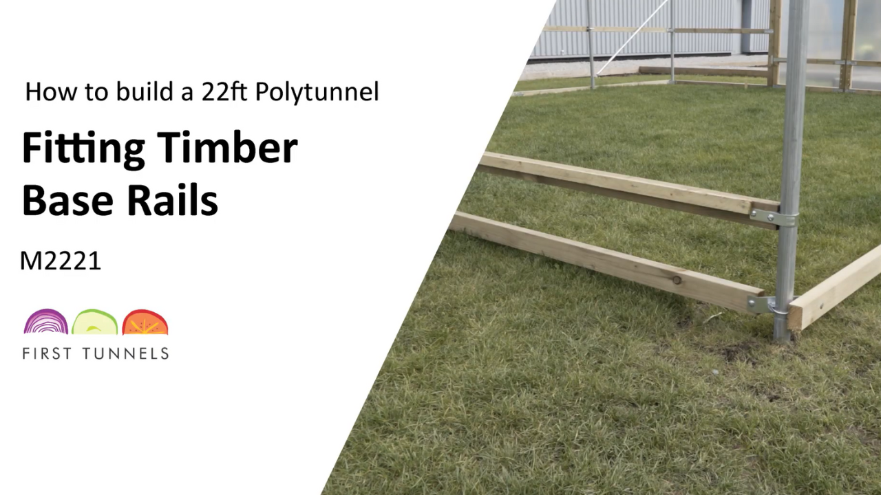
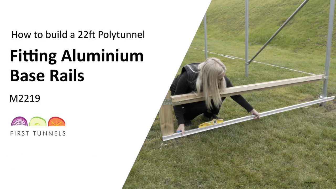
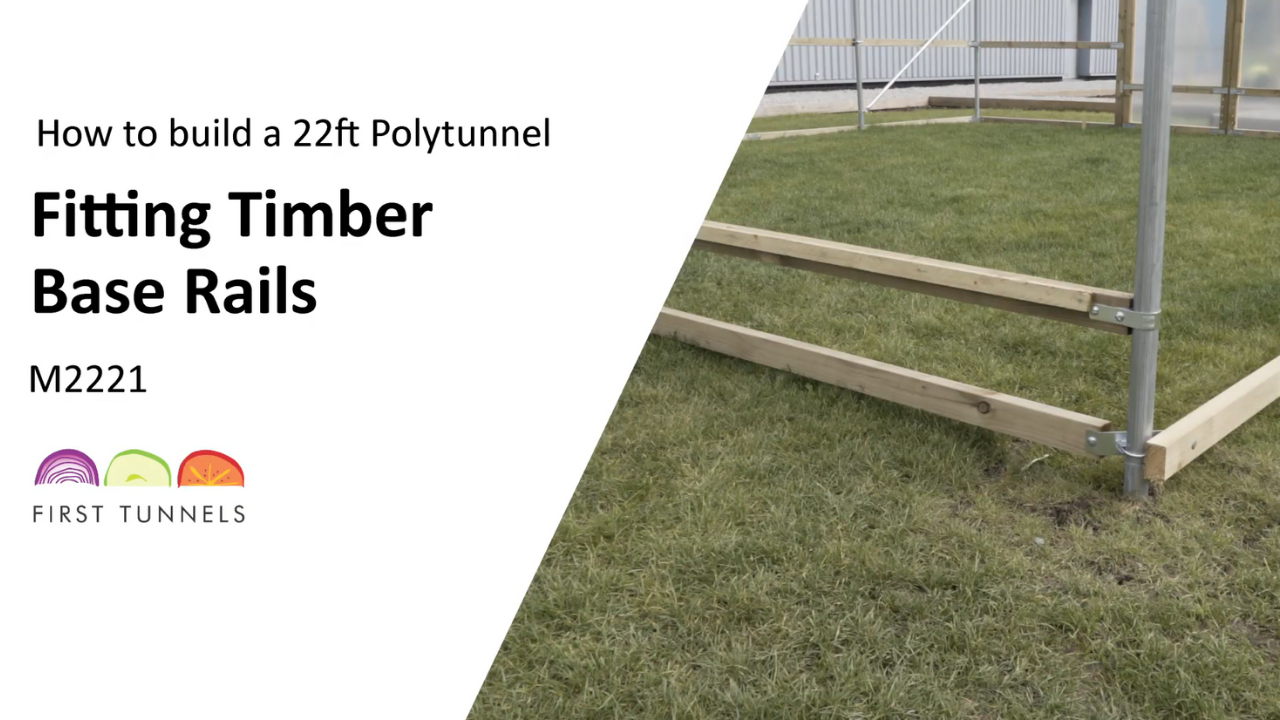
Timber side rails are 47mm x 75mm, commonly known as 3 by 2, and supplied in lengths of 1.6m,1.8m, 2.4m and 3.2m long (TBR16) (TBR18) (TBR24) (TBR32). The side rail is fitted 75cm above the base rail from the door post to the corner, down the length and returns to the opposite door post (fig 21a). It is fitted using the same method as fitting the base rail with corner (CCT50) and intermediate clamps (ICT50).
Measure from the top of the base rail up the hoop and make a mark at 75cm (fig 21b). This is the position where the bottom of your side rail will sit. Fit a corner clamp to the corner hoop (CCT50). To assemble the corner clamp, place the U bolt around the corner hoop with the threads pointing towards the inside of the polytunnel (fig 21c). Place the tube pressing then corner clamp onto the threads, ensuring the corner clamp wings are parallel to the width and length of your polytunnel. Loosely secure in place.
Locate a 1.8m (TBR18) length of timber and position it down the length of your polytunnel. Ensure the wing of the corner clamp is in the centre of the timber and that the timber is on the outside of the corner clamp wing (fig 21d). Make a mark through the hole of the corner clamp wing. Drill a hole through the mark using a 9mm timber drill bit. Push a bolt through the timber and corner clamp ensuring the thread is on the inside of the polytunnel. Adjust the clamp so that the bottom of the timber is level with the 75cm mark.
To secure the side rail to the intermediate hoop use an intermediate clamp. Ensure your side rail is to the height mark and drill a hole through the timber on each side of the hoop using a 9mm wood drill bit. Place a bolt through each of these holes from the intermediate clamps. An arched pressing is placed over the bolts and secured in place with nuts (fig 21e). To add another section you will need to join another piece of side rail to the one you have just fitted. To join the pieces of side rail you will be required to fit a nail plate to each side of the joint (NP3). Position a nail plate equally across the joint and then secure in place using square twisted nails (fig 21f). Work down the length of your polytunnel joining sections of 3.2m long side rail, finishing with a length 1.8m if required and securing them to the hoops using clamps.
To fit the side rail from the door post to the corner hoop. Use a length of timber 2.4m long (TBR24). Butt an end up to the inside of the corner clamp wing, make a mark through the hole and another mark where you are required to cut the piece in line with the door post. Drill a hole and cut the timber and then reposition the side rail. Secure it to the corner clamp using a washer and nut (fig 21g). Use a spirit level to make sure it is level to the door post. Use a 4mm timber drill bit to drill a pilot hole in the centre of the inside edge of the door post through into the corner rail. Screw a 150mm screw through the hole to secure together. Reinforce the joint from the door post to the side rail with a nail plate and square twisted nail (fig 21h). Nail plates are installed on both sides of the joint. Fit the side rail from the door post to the corner on the opposite end of the polytunnel using the same method. Cut off the excess flush with the end of the polytunnel.
Ventilation screens cannot operate around corners, and as a consequence, the ends underneath the corner side rail of the polytunnel adjacent to the doors, will be fitted with polythene panels (fig 21i). To start fit the polythene screen down the length of your polytunnel. From the end of the side rail on the length measure in 20cm and 40cm. Repeat this at the opposite end. The polythene screen will be fitted between the two 20cm marks. Roll out the polythene screen down the length and position it so one end is on the 20cm mark, ensure the polythene screen panel is flush with the top of the side rail and secure it using staples until you reach the 20cm mark at the opposite end. Once you have reached the other end use a piece of timber to cut the polythene screen to size. Use a straight edge to ensure you get a vertical cut (fig 21j).
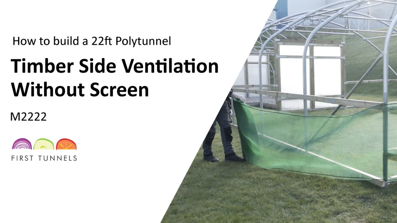
The corner polythene panels will be fitted to each end. Roll out the polythene panel and position it so one end is on the 40cm mark and around the corner leaving it overhanging the door post. Ensure the top edge is flush with the top of the side rail and staple the polythene panel to the side rail (fig 21k). Repeat on the opposite end. The ventilation netting can now be fitted. Staple the side ventilation net flush to the top of the side rail, ensure that the side ventilation net comes beyond each end hoop (fig 21l). If you have ordered timber side ventilation and screen for both sides of your polytunnel, repeat this process on the opposite side.
The next part of the process for installing side ventilation is done once you have fitted your polytunnel cover. This is because during the process of fitting the cover the rails are raised, the cover is attached and then the rails are lowered to add extra tension. Fitting ventilation before the cover has been fitted will hinder the process and will result in the ventilation netting becoming baggy. Please read the section on fitting the polytunnel cover to timber rails and then return to this section to perform the final fit of your ventilation and screen.
A timber post 47mm x 75mm 1.6m long should be cut to fit between the base rail and the side rail. This needs to be positioned flush to the outside of the end hoop. Secure in position to the side and base rail using the right-angled brackets and screws supplied in the side screen fixings kit. Repeat on the opposite end (fig 21m).
The gearbox winding system will be installed at one end of the tunnel. Decide which end of the tunnel you wish to have the winding mechanism. The large hole in the face plate goes to the bottom, insert 2 nuts into the gearbox housing and fix the gearbox into place using 40mm M6 bolts (fig 21n). Fix the gearbox onto the face plate so that the eye of the winder is positioned internally. Attach the runner wheels using two 25mm M8 bolts through the top and bottom holes of the face plate, secure in place tightly with a nut on to each bolt (fig 21o). Screw the runner wheels onto each thread with the nylon washer visible, ensuring the thread of the bolt is flush with the face of the runner wheels. Measure and cut the winder track to fit on to the corner post between the side rail and base rail. Slide the winder down into the track and screw into position on the inside of the corner post ensuring that the track is screwed to the inner edge of the post using 35mm long screws (fig 21p).
The screen tube is supplied in 1.57m lengths and is swaged at one end and plain at the opposite end. The screen tubes slot together. When fully assembled, the tube will exceed the length of your polytunnel. You will be required to trim the last piece to size. Starting with one tube, use a 5mm metal drill bit to drill a hole through the tube 7cm in from the plain end. Locate the drive pin into the tube, align the holes and bolt together with the 35mm M5 bolt and lock nut. Push the gearbox drive pin into the square drive hole in the gearbox (fig 21q). The remaining tubes should be slotted together, the final piece should be cut 2.5cm short of the vertical post at the opposite end of the winding mechanism. Finally, secure these tubes together using a self-drilling screw with the provided driver socket 4cm from the joint.
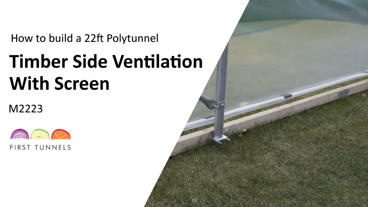
The polythene screen is fixed to the screen tube through the use of the clips. In order to aid fixing it is advisable to trim the polythene approx 30cm beyond the base rail (fig 21r/s). Working from the gear winder end, roll the polythene screen under and around the blind tube. Push a retaining clip onto the screen tube and proceed along the length of the polytunnel (fig 21t). Ensure retaining clips are fitted at each hoop. Fit the remaining clips in a position halfway between each hoop (fig 21u). Slide the hook onto the handle of the gear winder and turn, the gear winder should rise and fall as the ventilation screen opens and closes. If the screen tube needs adjusting, this can be achieved by wrapping more or less of the polythene around it.
With the screen now operational you can now fix the side ventilation net and corner polythene panels to the vertical post, door frame post and the base rail. First, a batten will need to be fitted to the two timber posts between the base rail and side rail on the outer face (fig 21v). This batten ensures the winding mechanism does not damage the ventilation netting. From the outside of the polytunnel, lift up the polythene panel and ventilation netting as high as possible. From this point, measure and cut a piece of batten to fit onto the post, it is not required to be the full height. Position this piece on the inner edge of the post, use a spare piece of batten as a spacer and position them so the spacer is flush with the outer edge of the timber post and then fix the batten into place with nails. Repeat on the timber post at the opposite end.
To aid fitting the corner panel around the corner, cut the corner panel parallel with the length of the polytunnel. Secure it to the base rail with staples. Secure the ventilation net to the base rail first. The ventilation netting is secured to the base rail using battens. To speed up the process we recommend pre-nailing a number of battens, nails should be 20cm apart and should not protrude. Starting in the middle and working out to each end pull the side ventilation netting down so it is tight and free of any wrinkles and creases, position a batten flush with the top of the base rail and nail into place. Now secure the ventilation netting to the timber upright. Pull the netting tight and secure a batten.
The corner polythene panel now needs fixing to the door post and base rail (fig 21w). Secure the side panel to the corner base rail and door post using the same method with pre nailed battens. Finally, trim off any excess polythene and net. Repeat this second step on the opposite side of your polytunnel if you have side ventilation with a screen on both sides.

